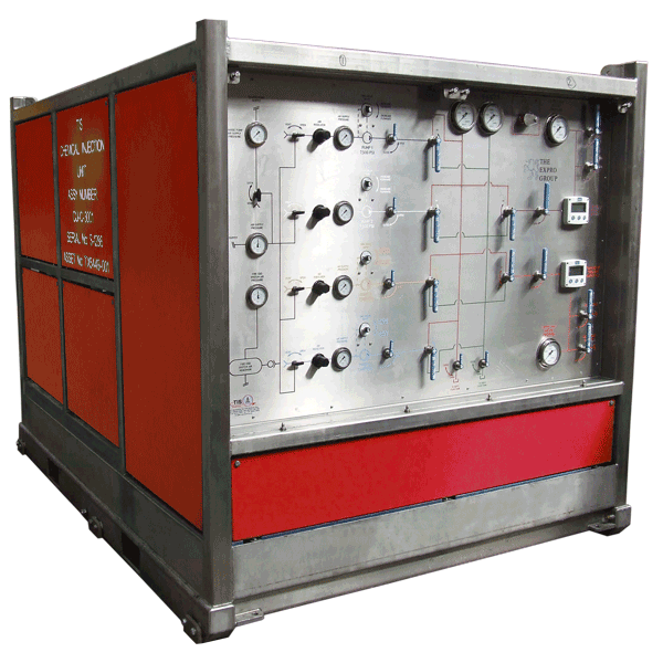
Chemical Injection Units
Hydraulic System
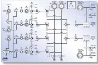
The hydraulic system is supplied with pressure from four air hydro pumps; each capable of running individually, this provides an available pressure head of up to 7,500 psi from two headers
Fluid Reservoir
The unit is fitted with a large capacity stainless steel reservoir; filtration is catered for by two parallel filters fitted to the downstream pipework, change over valves allows a filter to be on standby at any one time. Fluid level can be easily monitored from the sight glass on the front of the tank. The tank supply line has a ball valve fitted to allow line isolation. An access hatch allows for visual inspection of the inside of the tank
Pulsation Dampers
The unit is fitted with four bladder type pulsation dampers, one per pump outlet
Air Hydro Pumps
Four high output, low maintenance, single air head, double acting air hydro pumps are used to supply fluid under pressure directly to the system
Pneumatic System
Air supply to the pumps is achieved by using large bore pipework. Filters and moisture traps are fitted to remove any impurities from entering the system. A recommended air supply of 90 psi is required to run the pump efficiently
Fire Suppression system
The system includes an 80 litre AFFF foam tank which is situated behind a fire barrier. There is enough foam concentrate to produce 22,000 litres of mixed foam. The ESD buttons and a sacrificial plastic pipe which is situated around the upper level of the unit hold a normally open solenoid valve in the closed position; they are supplied with air from a dedicated reservoir. If the air pressure drops, either by the push of a button, or a fire melting the pipe then the solenoid opens, this valve is linked to the rig water supply. The water passes through an inductor which draws AFFF foam out of the storage tank and mixes it with the water on its way to the sprinkler heads
Instrumentation
The chemical injection unit has instrumentation that provides a 4-20 mA signal back to the PLC cabinet in the HPU. This consists of 4 pressure transducers that monitor the nitrogen buffer, the inlet air, header 1 and header 2 pressures. These readings are all duplicated by gauges that are mounted on the main control panel, with the exception of the nitrogen buffer which is located within the unit beside the nitrogen relief valve. A junction box provides an interface for a cable to run between the HPU and the CIU A level indicator is provided for a local visual indication of the tank fluid level
Links & Specs
Dimensions :
Length : 2,930mmWidth : 2,112mm
Height : 2,105mm
Gross Weight : 3,500kg
Dry Weight : 3,000kg
Tank Capacity : 700 litres
Instrumentation: Hy-lok
Operational Volume : 400 litres
Gas Blanket Pressure : 3 PSI
Main system max. working pressure : 7,500 psi
Main relief valves set : 8,250 psi
Pulsation Damper : Qty 4 @ 1 litre capacity
Pulsation Damper pre-charge : 1,000 psi nitrogen
Air Pump displacement : 49.2 cc per cycle
Filtration :
Pressure filters : Qty 2 @ 3 micronSuction strainers : Qty 4 @ 125 micron
Instrumentation :
Number of supply lines : 2Maximum rated working pressure : 7,500 psi
Fire Suppression System :
Tank Capacity : 90 litresOperational Capacity : 82.5 litres
t: +44 (0) 1224 775277 | f: +44 (0) 1224 729426 |
e: sales@tis-manufacturing.com
Kirkhill Place | Kirkhill Industrial Estate | Aberdeen AB21 0GU | UK
